| OptiLayer allows you to evaluate and to monitor averaged and integral spectral characteristics over arbitrary spectral or/and angle of incidence range.
These characteristics can be monitor in the course of analysis as well as during the design process. It is possible to monitor minimum and maximum values as well. Analysis –> Integrated values and characteristics |
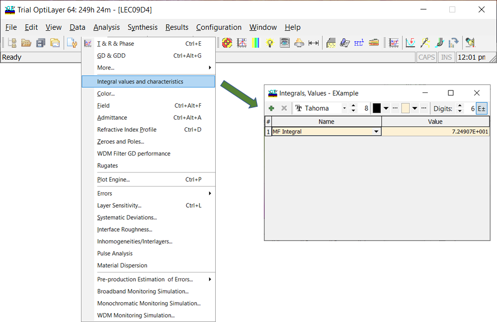
Fig. 1. By clicking Integrated values and characteristics, Integral, Values window opens. |
| Example. As an example, a 6-layer metal-dielectric coating was designed. The corresponding design bar is shown on the bottom of the Evaluation window (Fig. 5). The light reflectance from coating’s front and back side should appear as orange and violet. At the same time, solar transmittance of the coating is to be as large as possible. Color target and integral target are shown in Fig. 2 and Fig. 3, respectively. | |
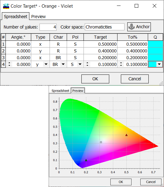
Fig. 2. Color target: color coordinates are specified CIE xyz (1931) color space. |
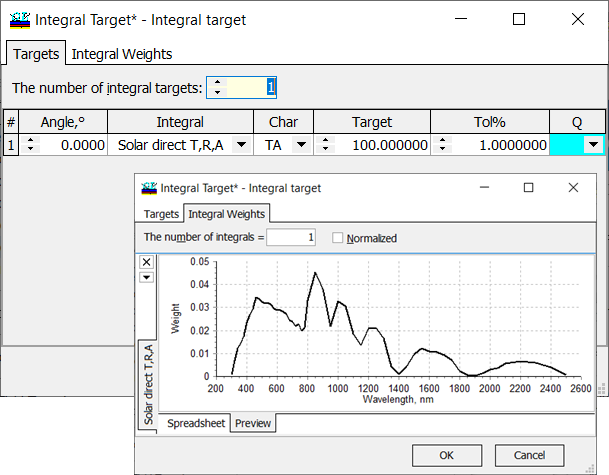
Fig. 3. Integral target: solar direct transmission should be maximized. The details are here. |
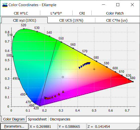
Fig. 4. Variations of the color coordinates of the designed coating (reflectance and back side reflectance) with respect to the incidence angle. Crosses show target values. |
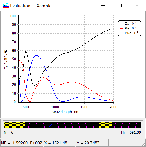 Fig. 5. Spectral performance (reflectance, back side reflectance , and transmittance) of the designed multilayer. Fig. 5. Spectral performance (reflectance, back side reflectance , and transmittance) of the designed multilayer. |
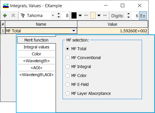
Fig. 6. By default, total merit function value is calculated. Using [+] and [x] buttons you can add or remove desired integrals/averaged values. The values are chosen from the pop-up list. |
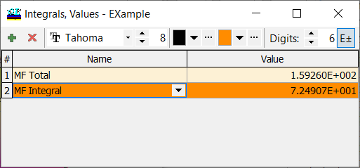
Fig. 7. Integral component of the merit function, \(MF_{int}\) is added for the calculation. OptiLayer allows to specify combined targets and optimize the design with respect many criteria simultaneously. |
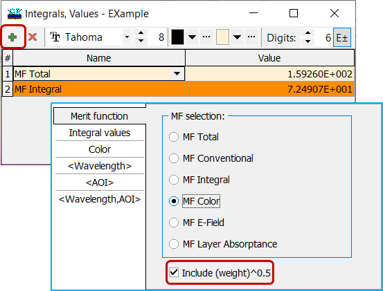
Fig. 8. Color component of the total merit function is being added. You can monitor the MF Color taking or not taking the weights into account. Integral weights can be specified in a special Target Weight window ( Data –> Target Weights) or directly in General Information window (Fig. 9). |
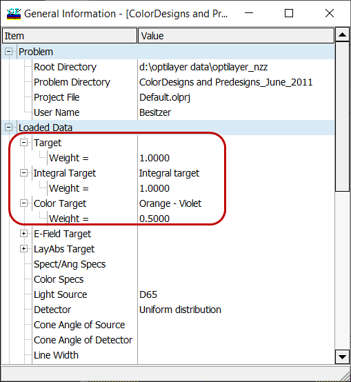
Fig. 9. Specification of target weights directly in General Information window. |
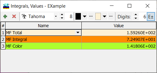
Fig. 10. Color component of the total merit function is added. Target weight of 0.5 is taken into account. |
Total merit function MF takes the form: \[ MF^2=0.5\cdot MF_{color}^2+MF_{int}^2 \]
|
| Along with different components of the merit function, OptiLayer allows you to display and monitor integral values. These values are calculated based on the spectral weight function \(W(\lambda)\) that can be chosen from the pop-up list.
All required spectral weights are to be specified in advance through integral target option (see Integral Target). As in Integral Target, there are two check boxes: Normalized and Use Source/Detector. Check or uncheck these boxes affects the integral calculations. Generally, when both boxes are checked, the integral \(F\) is calculated in the following way: \[ F=\frac{\int\limits_{\lambda_d}^{\lambda_u} W(\lambda)D(\lambda) S(\lambda) C(\lambda)d\lambda}{\int\limits_{\lambda_d}^{\lambda_u} W(\lambda) S(\lambda) D(\lambda)d\lambda},\] where \(\lambda_d\) and \(\lambda_u\) are boundaries of the wavelength interval of interest, \(W(\lambda)\) is a given weight function, \(S(\lambda)\) is a spectral characteristic of a coating, \(D(\lambda)\) and \(S(\lambda)\) are spectral distributions of the detector and light source, respectively. |
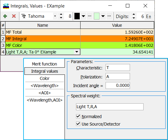
Fig. 11. Integral transmittance with normalized relative spectral distribution of illuminant D65 multiplied by the spectral luminous efficiency is specified. |
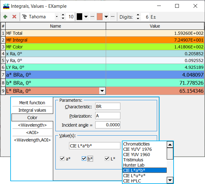
Fig. 12. Choice of the CIE L*a*b* color coordinates for calculation. |
You can monitor current color coordinates and not necessary those ones specified in the color target.
You can specify reflectance, back side reflectance, or transmittance; polarization states, and incidence angle. Integral calculations are performed in the stack mode as well. |
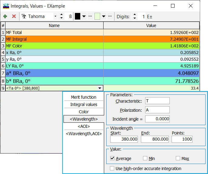
Fig. 13. You can calculate and monitor average values as well as maximum/minimum of spectral characteristics over a specified wavelength range. |
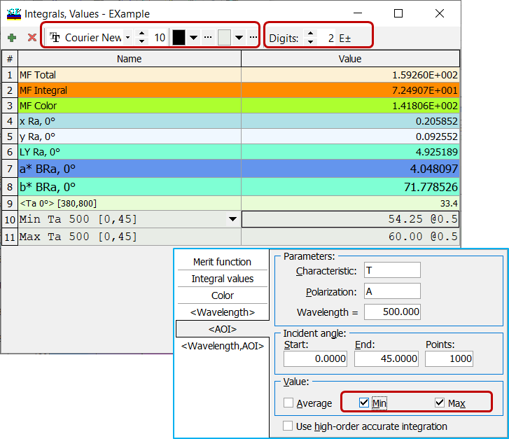
Fig. 14. It is also possible to display and monitor averaged spectral characteristics as well as their maximum/minimum over a specified angular range. |
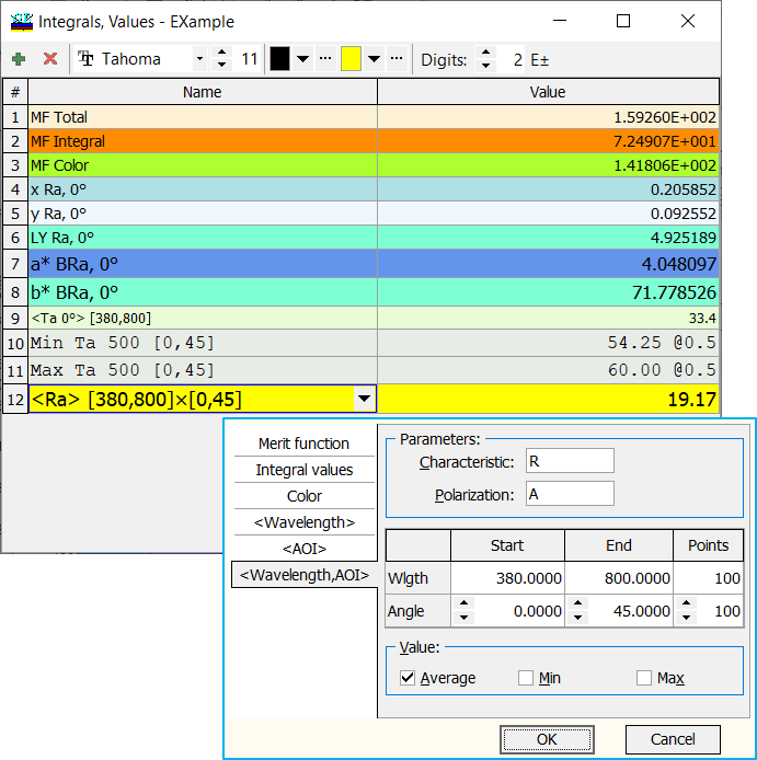
Fig. 15. Reflectance data averaged over the visible range and the angular range. |
It is also possible to display and calculate averaged spectral characteristics as well as their maximum/minimum over a 2D region of [wavelengths x angles of incidence].
Computations of 2D average values is more time-consuming, thus it is recommended to select a moderate number of points for each of dimensions. |
|
It is possible to adjust font type, size, font color and background color using corresponding toolbar controls. Also it is possible to change the number of digits to display and to select scientific format when necessary (use [E±] button for this purpose). You can save your style using Save Style as Default and then Apply Default Style in another problem directory (starting from Version 12.83). Of course, you can turn back to the Build-in Style. |
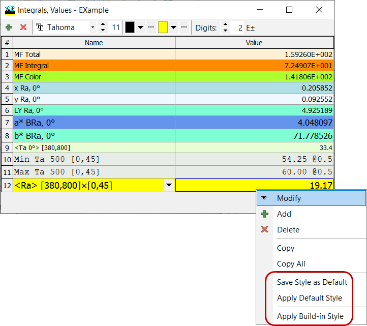
Fig. 16. Using the right mouse button, you can open a sub-menu allowing you to save and restore styles. |
Look our video examples at YouTube
OptiLayer videos are available here:
Overview of Design/Analysis options of OptiLayer and overview of Characterization/Reverse Engineering options.
The videos were presented at the joint Agilent/OptiLayer webinar.