|
Rugate options of OptiLayer allows you to analyze and synthesize rugate coatings. Rugate coatings can be described by analytical expressions giving dependence of the refractive index on the coating thickness. Also, rugate coatings can be described as arbitrary smoothe refractive index profiles. For a theoretical analysis and design, a rugate coating structure can be approximated by a refractive index profile with a larger number of steps. Design of rugates requires an efficient method to specify the structure, calculate spectral characteristics and optimize the structures. OptiLayer allows you fast and effective designing rugate filters.
|
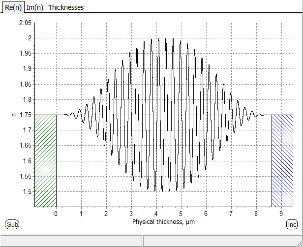
Fig. 1. Refractive index profile of the rugate filter specified by a formula below. Refractive index profile, transmittance and formula representation of the rugate presented in B.H. Southwell, “Extended-bandwidth reflector designs by using wavelets”, Appl. Opt., 1997, Vol. 36 |
|
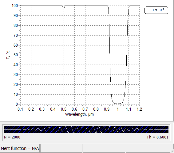
Fig. 2. Transmittance of the rugate filter shown in Fig. 1: ripples in high transmittance zone are suppressed. |
\(n(x)=n_a+0.5 n_p A(x) \sin\left(\displaystyle\frac{4\pi x}{\lambda_0}\right)\) \(A(x)=10 t^3-15 t^4+6 t^5 \) \(t=\displaystyle\frac{2x}{TOT},\;\;\mbox{ if}\;\; x<\frac{TOT}{2} \) \(t=\displaystyle\frac{2(TOT-x)}{TOT},\;\;\mbox{ if}\;\; x>\frac{TOT}{2}\) Here x is thickness coordinate, TOT is total optical thickness.
|
Design of Rugates |
|
|
Rugate filters are optical coatings with the refractive index which is varied continuously. In comparison with conventional multilayer structures, rugate filters provide some special potentials:
|
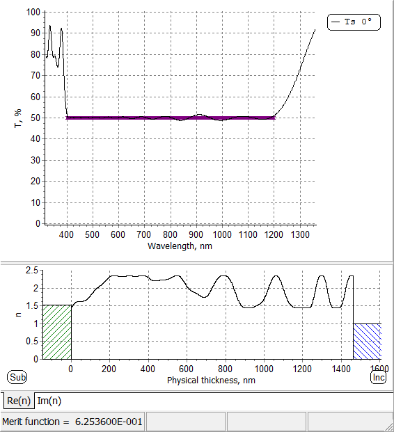 Fig 3: designed beam splitter with the help of rugate filter design option. |
|
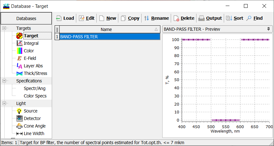
Fig. 4. A bandpass filter target. |
Design example: A bandpass filter should reflect the light in the range 500-600 nm and transmit the light in the ranges 400-500 nm and 600-700 nm (Fig. 4, right pane). Refractive indices of layer materials are 2.35 and 1.45. |
|
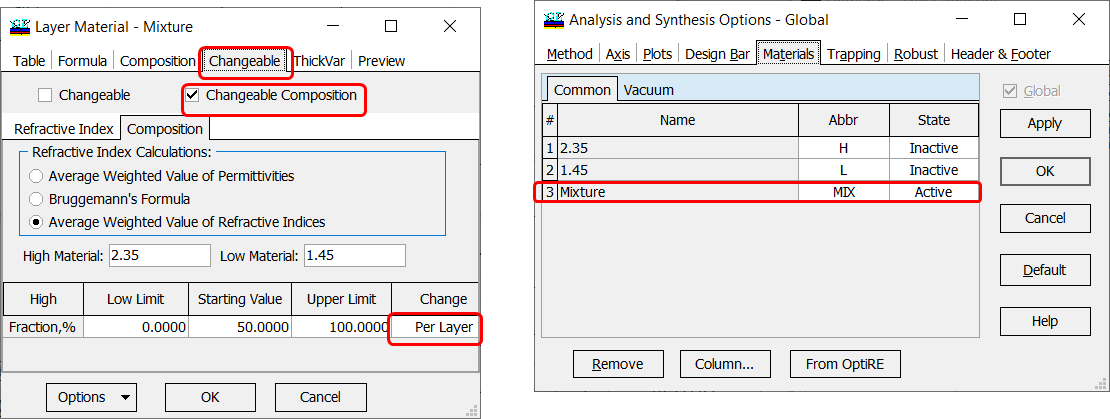
In OptiLayer the dependence of the refractive index is described with the help of fraction function on the basis of Changeable Composite material. Changeable Composite material is a mixture of two materials, that we will call high- and low-index materials. If Change option of such material is “Per Layer” it can be used for the rugate filter description. Therefore it is necessary to create and load to memory at least one Layer material that is Changeable Composite. For easy creation you can use “Create!” button of the Rugates dialog that will invoke Create Material Assistant for you. |
Fig. 5. Changeable material based on two materials with refractive indices 2.35 and 1.45. The intermediate refractive index is calculated using averaged weighted value of refractive indices. This changeable material should be loaded. Important: State of this material should be Active and states of other materials must be Inactive (Fig. 5, right pane). Important: Change status should be Per Layer (Fig. 5, right pane). |
|
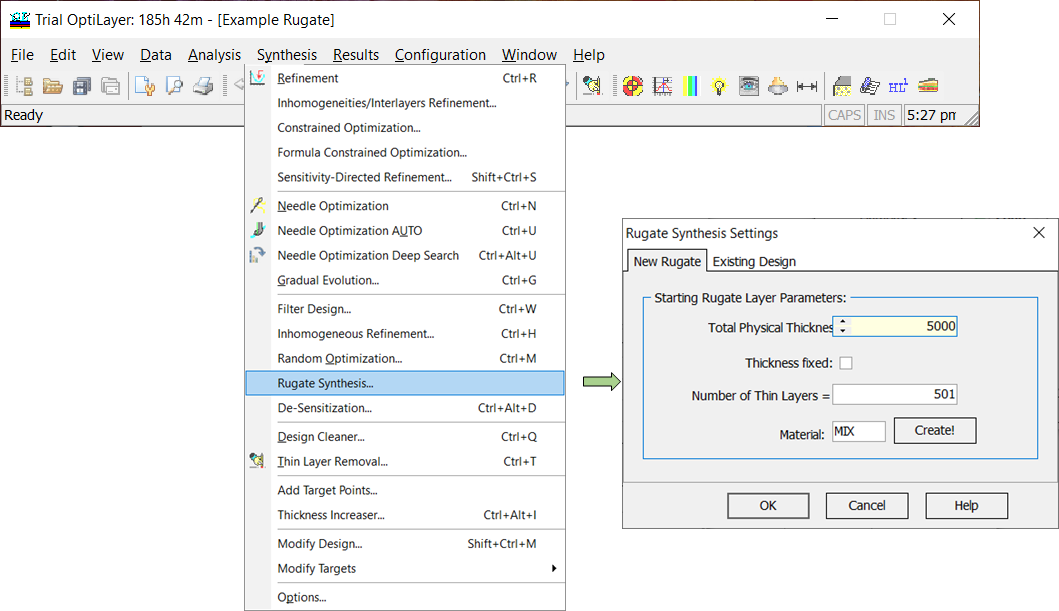
Fig. 6. A starting rugate (one layer of the changeable material MIX) is chosen. The thickness of the rugate is 5000 nm. The profile will be described by 501 thin layers. |
You can run rugate design using Rugate Synthesis option: Synthesis –> Rugate Synthesis. In the Rugate Synthesis Settings, you should specify an initial coating thickness and the number of thin layers approximating the rugate profile. Also, you need to choose a changeable material. If you do not have any changeable material, you can create it using Create! button. |
|
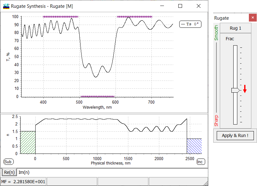
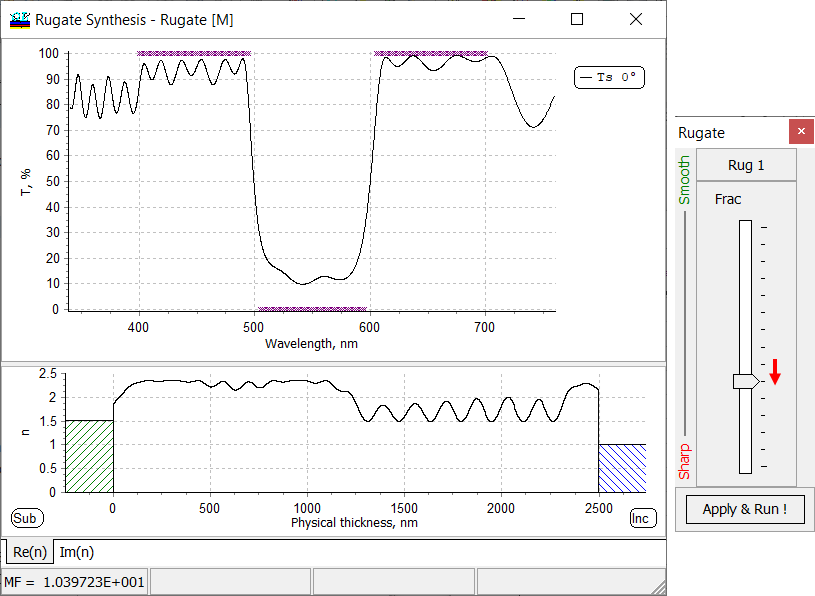
Fig. 7. Transmittance (upper pane) and refractive index profile of the rugate filter after the first step. In order to achieve better performance, the slider (right pane) should be moved one step downwards, in the “Sharp” direction. |
Fig. 8. Animation of the design process (step 1). |
|
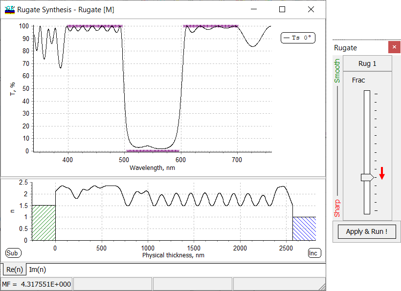
Fig. 9. Animation of the design process (step 2). |
Fig. 10. Transmittance (upper pane) and refractive index profile of the rugate filter after the second step. In order to achieve better performance, the slider (right pane) should be moved one step downwards, in the “Sharp” direction. |
|
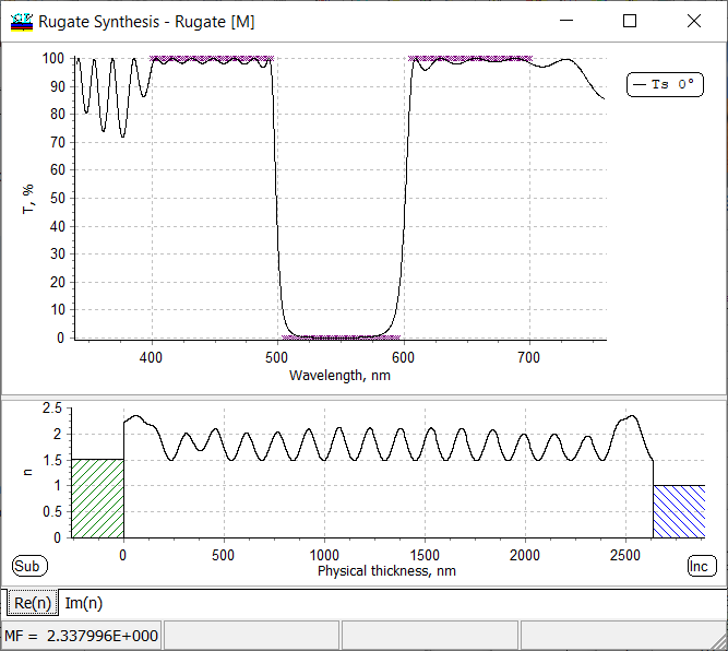
Fig. 11. Transmittance (upper pane) and refractive index profile of the rugate filter after the third step. In order to achieve better performance, the slider (right pane) should be moved one step downwards, in the “Sharp” direction. |
Fig. 12. Animation of the design process (step 3). |
|
Fig. 13. Transmittance (upper pane) and refractive index profile of the rugate filter after the final step. |
The obtained rugate design can be saved in a standard way: Data –> Save data –> Save design |
|
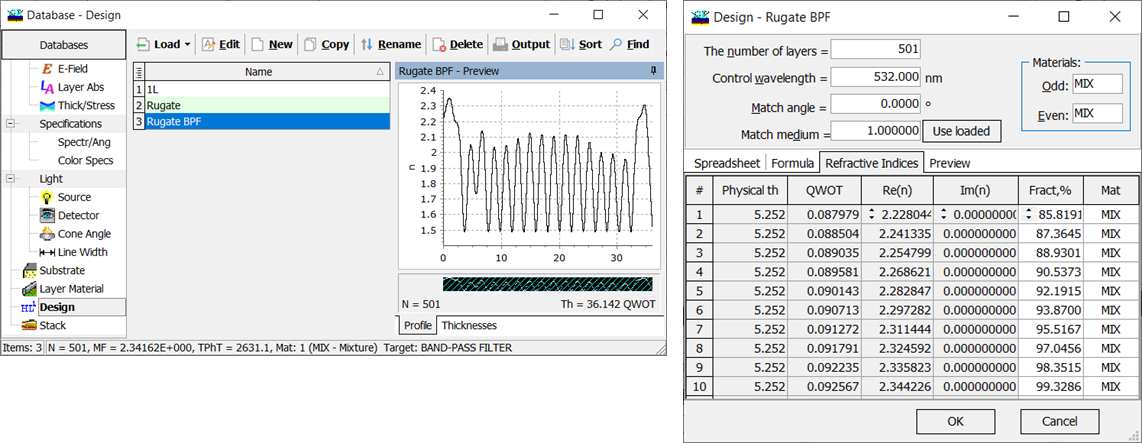
The rugate coating structure is approximated by a refractive index profile with a larger number of steps. In the rugate design spreadsheet (Fig. 14, right pane), you can see thin layers and corresponding fraction values.
Fig. 14. Saved Rugate BPF design: its profile (in the middle) and structure (right pane). |
|
|
In order to calculate a rugate spectral characteristic (reflectance or transmittance, absorptance etc.), the refractive index profile is subdivided into segments (thin layers). OptiLayer evaluates spectral characteristics of this profile. Due to unique mathematical algorithm of OptiLayer including Tikhonov’s regularization, rugate profile will be a smooth function. It is know from the thin film theory that in the case of normal incidence and s-polarization, two-component designs consisting of alternative high and low index materials (conventional multilayers) provide optimal design solutions. Due to this reason, using a too smooth rugate profile it is not possible to achieve target specifications (for example, steps 1 and 3 in the example above, Figs. 7, 10). In this case, in order to achieve target characteristics, the smoothness requirement can be relaxed using special sliders (see Figs. 7, 10, 11). Moving the sliders downwards in the direction “Sharp” will lead to less smooth profiles. At the end of the designing process, a compromise between smoothness of the profile and achievement of target specifications should be found. |
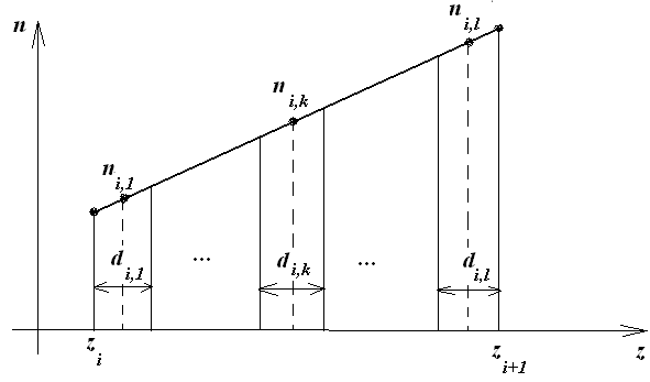
Fig. 15. Subdivision of rugate refractive index profile by thin layers. In the example above (bandpass filter), the rugate was described by a refractive index profile subdivided by 501 thin layers. |
|
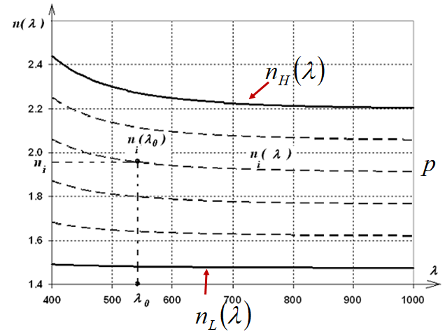
Fig. 16. Dispersion of mixture materials: dispersion curves \(n_i(\lambda)\) are between refractive indices of high- and low-index materials. Each dispersion curve corresponds to a fraction \(p\). |
In the case when in Refraction index calculation, Averaged Weighted Value of Refractive Indices (Fig. 5) is chosen, refractive index of every thin layer is calculated as a linear combination of high and low refractive indices (Fig. 16): \[ n_i(\lambda)=p n_H(\lambda)+(1-p) n_L(\lambda)\] The parameter \(p\) is a fraction of materials. \(p\)-value of 0 corresponds to \(n_L(\lambda)\), \(p=1\) corresponds to \(n_H(\lambda)\). If in Refraction index calculation, Bruggemann’s Formula (Fig. 5) is chosen, then refractive index of every thin layer is calculated according to Bruggemann’s formula. \[ n_i=0.5 \sqrt{\alpha^2 (p)+\sqrt{\alpha^2 (p)+8n_H^2n_L^2}},\] where \[\alpha=(3p-1)n_H^2+(2-3p)n_L^2 \] |
|
You might be interested in the following publications:
|
|
OptiLayer provides user-friendly interface and a variety of examples allowing even a beginner to effectively start to design and characterize optical coatings. Read more…
Comprehensive manual in PDF format and e-mail support help you at each step of your work with OptiLayer.
If you are already an experienced user, OptiLayer gives your almost unlimited opportunities in solving all problems arising in design-production chain. Visit our publications page.
Look our video examples at YouTube
OptiLayer videos are available here:
Overview of Design/Analysis options of OptiLayer and overview of Characterization/Reverse Engineering options.
The videos were presented at the joint Agilent/OptiLayer webinar.