 |
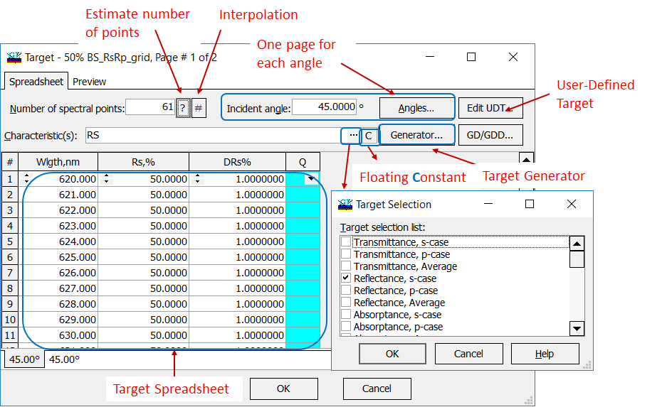
OptiLayer allows you to specify all possible target characteristics. Target Window can be used to enter and to edit target data. In the information fields you should specify the number of spectral points at which target data will be entered, the incidence angle(s) at which data will be entered, and the type of spectral characteristic(s) for which data will be supplied.
For each angle of incidence (AOI) you can specify a separate spreadsheet (first column is a spectral unit, for example, wavelength). On the contrast, in angular mode for each wavelength you specify a separate angular page (first column is AOI). Additional features are target generator, interpolation of target function (increase the number of grid points), estimation of the required number of spectral points, User-Defined Target (UDT) and special editor for group delay/group delay dispersion (GD/GDD). OptiLayer provides wavelength grids of three different types. |
Each target spreadsheet contains:
OptiLayer constructs a merit function automatically in the correspondence with the specified target data: \[ MF^2=\frac 1K\sum\limits_{i=1}^K \frac 1L\sum\limits_{j=1}^L \left[\frac{S(X; \theta_i;\lambda_j)-\hat{S}(\theta_i;\lambda_j)}{\Delta_{i,j}}\right]^2,\] where \(S\) is the theoretical spectral characteristic, \(\hat{S}\) is the target spectral characteristic, \(\{\lambda_j\}, j=1,…,L\) is the wavelength grid, \(\{\theta_i\}, i=1,…,K\) is the angular grid, \(\Delta_{i,j}\) are target function tolerance values, \(X\) is the vector of design parameters. |
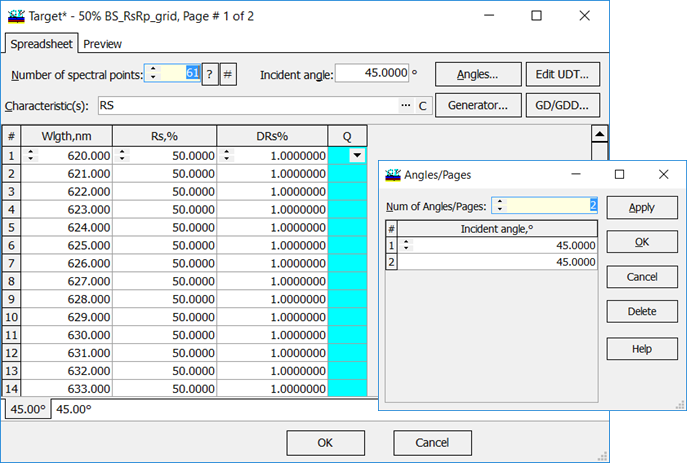
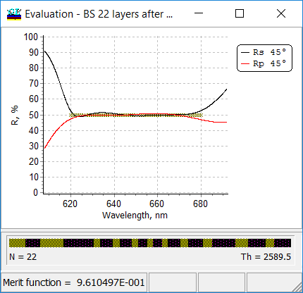
Example: target spreadsheet corresponding to a beamsplitter design: target \(R_s=50\%\), \(R_p=50\%\). Spectral range is from 620 nm to 680 nm, AOI=\(45^0\), 61 spectral points. |
 |
List of available target spectral characteristics includes:
|
| Target Generator is a powerful feature of OptiLayer allowing you to create conventional and range targets of the complicated structure. Typically such targets contain specifications fora number of angles of incidence, different spectral ranges and different sets of spectral characteristics.
Example (right panel): Rs=Rp=0 in the range from 510 nm to 520 nm, Rs=Rp=100% in the range from 1000 nm to 1500 nm. Design tolerances equal to 0.1 in the vicinity of the wavelength 500 nm. It means that this spectral range is more important for the design problem. Wavelength grid is linear around the wavelength 500 nm and logarithmic in the spectral region from 1000 nm to 1500 nm. The number of spectral points is 11 in the first spectral range and it is 128 in the second one. |
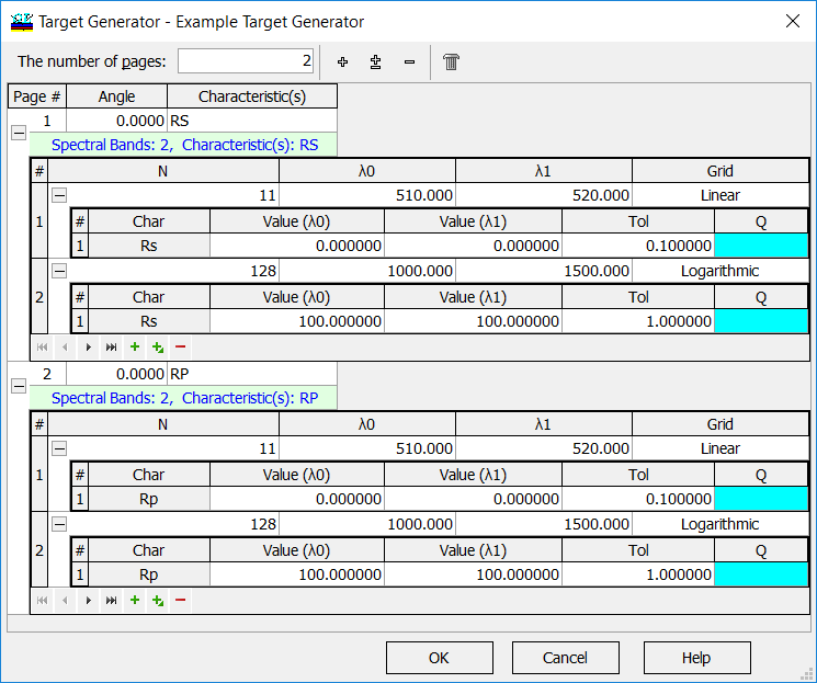 |
| In this example the merit function is calculated as follows:
\[ MF^2=\frac 1{11}\sum\limits_{j=1}^{11}\left(\frac{R_s(X;\lambda_j)}{0.1}\right)^2+\frac 1{11}\sum\limits_{j=1}^{11}\left(\frac{R_p(X;\lambda_j)}{0.1}\right)^2+\frac 1{128}\sum\limits_{i=1}^{128}\left(R_s(X;\lambda_i)-100\%\right)^2+\frac 1{128}\sum\limits_{i=1}^{128}\left(R_p(X;\lambda_i)-100\%\right)^2 \] |
|
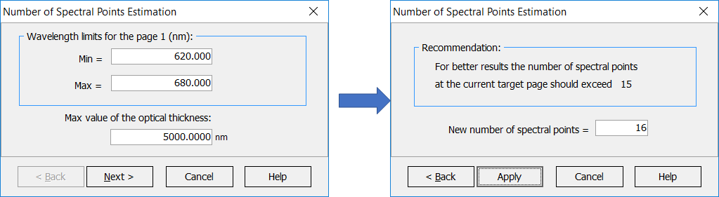 |
It is possible to estimate the number of spectral points required for the current spectral target in order to perform design synthesis efficiently. Using too small number of points will lead to bad approximation of the desired target requirements (undesirable “leaks”, peaks in the spectral characteristics of interest). Using too many spectral points will slow down computations accordingly. |
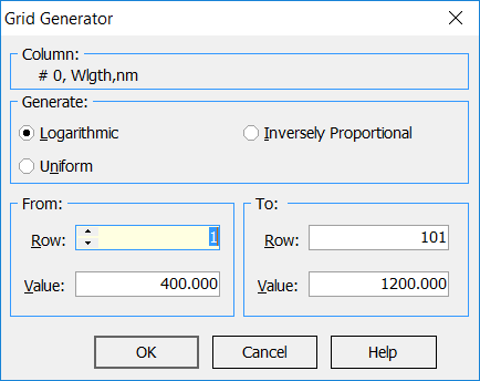
| OptiLayer provides linear, logarithmic and inversely proportional wavelength grids. The wavelength grid can be automatically specified with the help of a user-friendly grid generator:
|
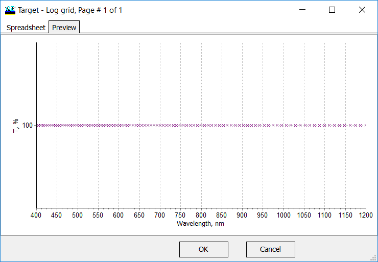
Logarithmic grid is more sparse in the longer wavelength range and more dense in the shorter wavelength region. |
OptiLayer provides user-friendly interface and a variety of examples allowing even a beginner to effectively start to design and characterize optical coatings. Read more…
Comprehensive manual in PDF format and e-mail support help you at each step of your work with OptiLayer.
If you are already an experienced user, OptiLayer gives your almost unlimited opportunities in solving all problems arising in design-production chain. Visit our publications page.
Look our video examples at YouTube
OptiLayer videos are available here:
Overview of Design/Analysis options of OptiLayer and overview of Characterization/Reverse Engineering options.
The videos were presented at the joint Agilent/OptiLayer webinar.