| OptiLayer has a variety of options for constrained optimization. These options are aimed to meet various feasibility demands and to provide better manufacturing properties of coating designs.
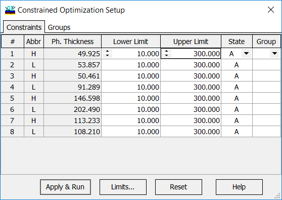
For example, it is possible to specify boundary of layer thicknesses. It is possible to set constraints for individual layer thicknesses. Each layer can have:·
state, which indicates whether the thickness of this layer can vary during optimization. If the state is Optical Fixed, the physical thickness and refractive index vary but only so that their product, i.e., optical thickness, remains constant. |
 |
Example 1. Optimization a solar cell structure |
|
| Optimization of a solar cell structure using Constrained optimization option of OptiLayer. Initial design: 5-layers solar cell. Note that upper SnO2 layer is adjacent to the BK7 glass and light incidence from the BK7 glass is considered.
|
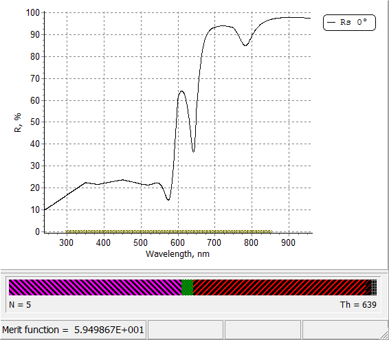 |
| Only thicknesses of two layers (internal amorphous silicon layer and top SnO2 conducting layer) are allowed to vary in the specified limits: from 150 to 600 nm and from 10 to 100 nm, respectively. | 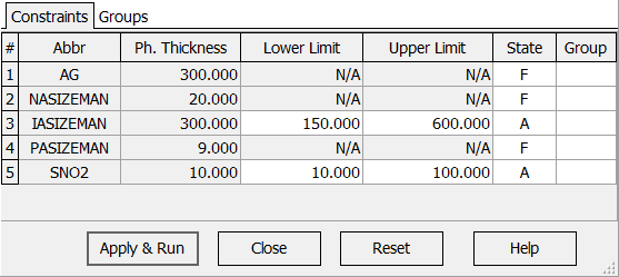 |
Example 2. Design of mirrors using quasi-rugate filters |
|
|
Quasi-rugate filter a multilayer: • that may have layers with variable refractive indices limited by refractive indices of low and high index materials; • that does not contain thin layers; • with refractive index profiles resembling a rugate refractive index profiles • with spectral properties typical for rugate filters For the design procedure a special material, so called changeable material, with variable refractive index is used. The design procedure is based on the constrained optimization of a special type. Constrained optimization is used in order to limit layer thicknesses and obtain designs without thin layers. |
|
| Design of the mirror with the suppressed second high reflection zone | |
|
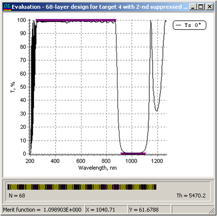
Two-component (classical) solution
Transmittance of 68-layer two component mirror. |
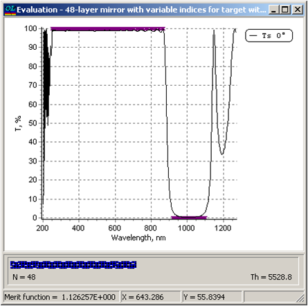
Quasi-rugate solution
Transmittance of a quasi-rugate design. |
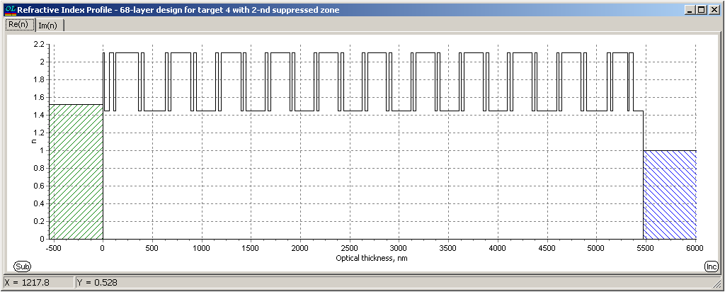 Structure of 68-layer two-component design Structure of 68-layer two-component design |
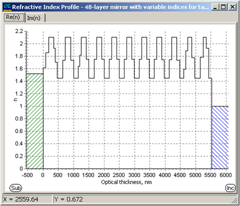 Refractive index profile of quasi-rugate solution Refractive index profile of quasi-rugate solution |
| Learn more in: A.V. Tikhonravov, M.K. Trubetskov, and T.V. Amotchkina, “Application of constrained optimization to the design of quasi-rugate optical coatings,” Appl. Opt. 47, 5103-5109 (2008). | |
Example 3. Design of quasi-rugate minus-filter |
|
| Constrained optimization option allows you to design multilayers with quarter-wave optical thicknesses of coating layers. For the design procedure a special material, so called changeable material, with variable refractive index is used. The design procedure is based on the constrained optimization of a special type. Constrained optimization is used in order to obtain designs consisting of quarter-wave layers. | |
 |
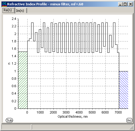 |
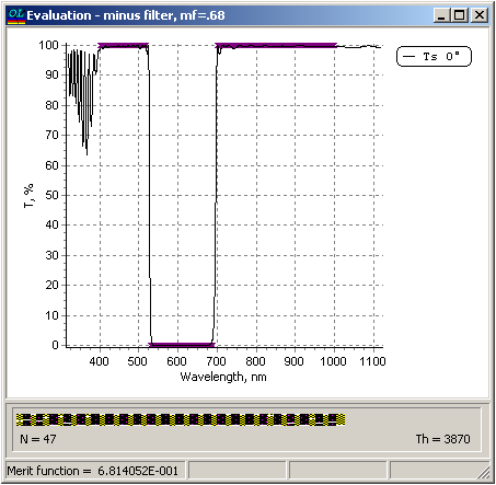
| Transmittance of 47-layer quasi-rugate minus filter | Refractive index profile of 47-layer quasi-rugate minus filter. All layers have quarter-wave optical thicknesses |
| Learn more in: A.V. Tikhonravov, M.K. Trubetskov, and T.V. Amotchkina, “Application of constrained optimization to the design of quasi-rugate optical coatings,” Appl. Opt. 47, 5103-5109 (2008). | |

