| Thin Film Removal procedure is one of the production friendly design options of OptiLayer:
Synthesis –> Thin Film Removal This procedure allows you to remove thin layers from the obtained design. The Thin Layer Removal window shows expected merit function values after removing various design layers (MF increase column). Layers in the list box are sorted by their physical thickness values in the ascending order. In Automatic mode Thin Layer Removal will work until one of termination criteria is fulfilled. Termination criteria include termination on the bases of allowed increase of the merit function value or/and termination when there is no layers thinner than a given value. Exclude material(s) list allows to exclude some materials from consideration. It is useful if thin metal layers present in the design. Example. Designing a beamsplitter:
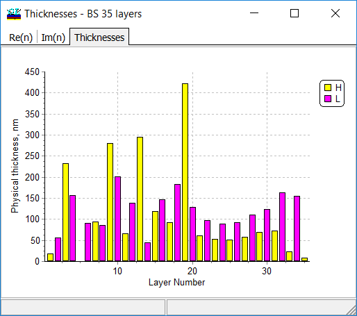
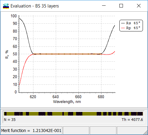
A 35-layer design can be easily obtained with the help of the Needle Optimization Technique (see Rp/Rs and refractive index profile at the right panel). It is seen that design reflectances perfectly approximate target characteristics. At the same time, the design contains several very thin layers. Thin Film Removal can be used to remove thin layers and keep the excellent approximation of target reflectance by design reflectance.
|
|
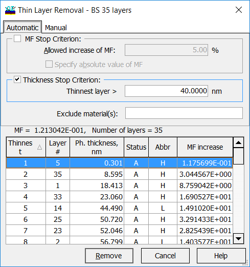 |
It is seen (left panel) that the design contains 2 layers thinner than 10 nm and 5 layers thinner than 50 nm.
In this example, a low limit for thicknesses of design layers is 40 nm. Of course, it is assumed that the low limit is a reasonable value. Low boundary higher than 50 nm would lead to significant worsening of the merit function. |
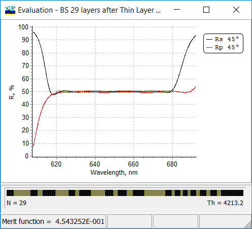
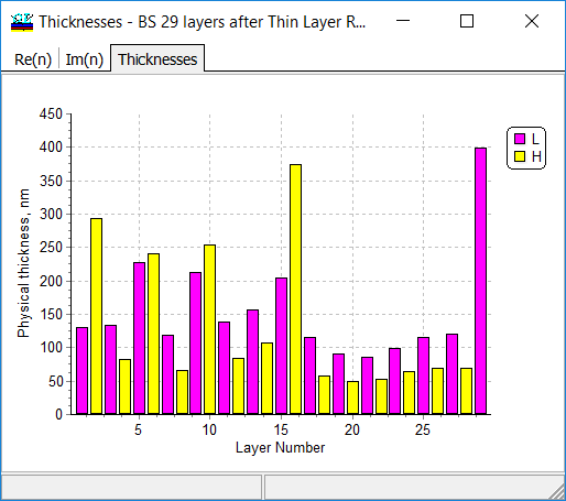
| As a result, a 29-layer design has been obtained. Correspondence between target and design spectral reflectance is still excellent.
|
At the same time, the thinnest layer is 49.5 nm.
|
Design Cleaner
| The Design Cleaner option is intended for an automatic simplification of designs obtained by OptiLayer refinement and synthesis routines.
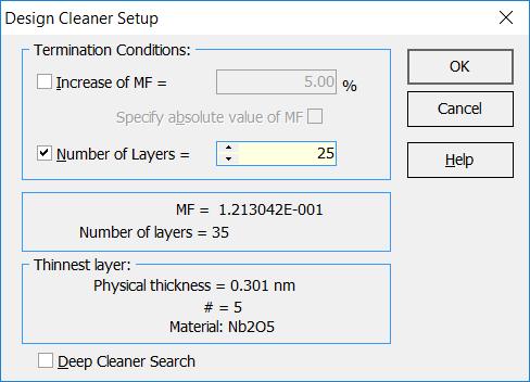
Synthesis –> Design Cleaner The Design Cleaner allows you to reduce the number of design layers by the removal of those layers, which excluding from the design with subsequent design reoptimization causes only a small effect on the merit function value. The main stop criteria for the Design Cleaner are the relative Allowed increase of MF measured in percentage and number of layers.
In the example, 25 layers is specified as a low boundary of the number of layers. |
Example. Designing a beamsplitter:
A 35-layer design can be easily obtained with the help of the Needle Optimization Technique (see Rp/Rs and refractive index profile below).
|
As a result, a 25-layer design can be obtained. 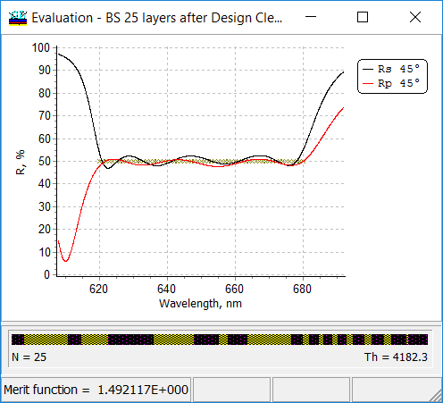 |
This design contains, however, one layer of 15 nm thickness.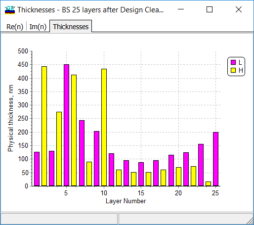 |
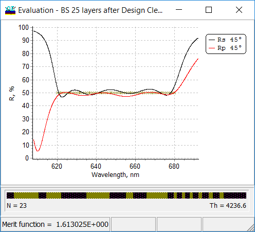
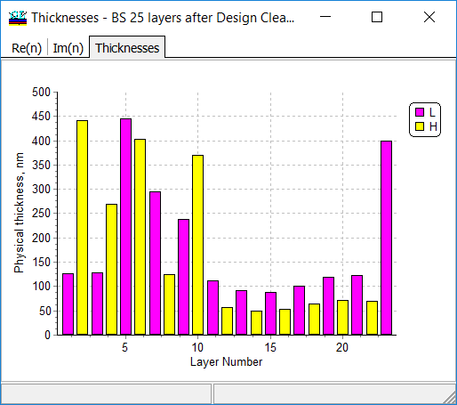
| Then Thin Layer Removal procedure can be applied and 23-layer design is obtained.
|
The thinnest layer is now of 50.2 nm thickness.
|

